Designing and aligning optical systems incorporating liquid crystal spatial light modulators (SLMs)
For citeable PDF versions of this document, please use the links below.
- DOI (concept): https://doi.org/10.5281/zenodo.3664145
- DOI (version): https://doi.org/10.5281/zenodo.3664146
- Authors: Patrick Salter, Martin Booth
- Last modified: 5 yrs ago
The listed authors have participated in the writing of this document. As the content is the culmination of long term work in the Dynamic Optics and Photonics Group, many others have contributed directly or indirectly to this material. We consciously acknowledge all of these contributions, even though it is impractical to list them all here
Introduction
A spatial light modulator (SLM) is a device that can control the spatial distribution of the properties of light across the profile of a beam. The term SLM most often refers to a liquid crystal based device, which is electrically controlled, pixelated and is used to control the phase of the light. Most of the common modern SLMs are of the liquid crystal on silicon (LCOS) type that operate in reflection mode. SLMs can be useful for a range of applications such as parallelization (the generation of multiple foci) or shaping the focal intensity distribution (either for aberration correction or generation of exotic foci such as Bessel or Airy beams). This document outlines some basic tips for effective use of SLMs in optical systems, including hints on optical layout, alignment and addressing. The document is aimed at those with experience in optical engineering but who are new to SLM operation. The information provided here is not intended to be a thorough review, but it should be sufficient help people new to the field to get started with this technology.
SLM background
The SLM is normally operated as phase-only, meaning that it simply modulates the phase of an incident light beam. To achieve this, it is important that the device is illuminated with linearly polarized light and that the incident polarization is aligned completely with the fast axis of the device (the manufacturer will indicate which direction this is relative to the device in the manual). If the polarization is not well oriented, not all the light will be phase modulated and there will be a change in polarization state. It is possible to operate the device for both amplitude or polarization modulation but this is more complicated and/or usually less efficient, such that we will not cover it here.
Liquid crystal devices can only provide phase modulation over a limited range, which is normally fixed in the interval 0→2π radians. However, it is still possible to display large amplitude phase shapes by wrapping the phase in adjacent pixels, with a discontinuous jump from 0→2π, such that any arbitrary phase shape can be effectively displayed by conducting a modulo 2π operation. The possibility for displaying phase discontinuities additionally generates many further in options in beam shaping.
Modern SLMs have much improved power handling capabilities, but engineers should still proceed with caution when selecting a SLM for high power applications by checking damage thresholds. Some suppliers offer actively cooled devices which operate much better at higher incident powers. When using incident power > 100mW or pulsed lasers, it is important to remember to expand the laser beam prior to the SLM and certainly not to focus the beam onto the SLM display.
This document describes the use of SLM devices in spatial shaping of a light beam. We note that SLM devices are also frequently applied to temporal shaping of ultrashort pulses, by placing the device in a location where there has been a large degree of spatial chirp engineered. This is outside the scope of this document, and will not be covered here.

SLM optical system
-
Modern SLMs commonly operate in reflection. It is typical that the angle of incidence for the input beam should be less than 10°. It is possible to operate them at normal incidence using beam splitters, but we have not noticed any degradation in performance using small angle illumination and it makes the design simpler and more efficient.
-
It is important not to focus the beam on the SLM or there is a risk of damage. Indeed, it is typically useful to expand the beam prior to SLM, to achieve uniform illumination over the active area of the beam.
-
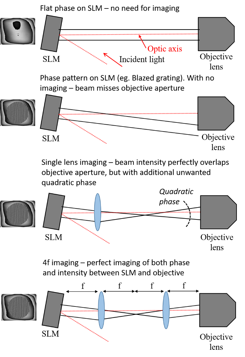
The SLM displays phase patterns. For many applications it is important to relay this phase pattern to another point in the optical system, which is done using a pair of lenses in a 4f configuration (Figure 2). A common example is where the SLM phase is imaged onto the back focal plane (pupil) of an objective lens, which is appropriate for many forms of aberration correction, parallelization and beam shaping. This is the situation we will concentrate on here.
-
If there is no imaging stage between SLM and objective lens, the light diffracts after the SLM and changes the illumination distribution at the objective lens. The calculated phase patterns displayed on the SLM are no longer effective.
-
It is possible to image the SLM onto the objective with just a single lens. This is effective at imaging intensity, but adds an additional quadratic phase which is unwanted.
-
Imaging the SLM onto the objective in 4f configuration relays an accurate representation of both the intensity and phase distribution at the SLM.
-
By choosing different focal length lenses in the 4f configuration, it is possible to magnify/demagnify the SLM relative to the objective.
-
It is desirable to use as much of the SLM as possible for a given situation. However, the SLM should at least fill the objective pupil aperture and it can also aid the alignment if there is a small amount of room for adjustment.
-
It is possible to estimate the physical size of the pupil aperture for an objective lens as Pupildiameter = 2*NA*fobj = 2*NA*fTL/M, where NA is the objective numerical aperture, and fobj it’s effective focal length. fTL is the focal length of the tube lens the objective is designed to work with (manufacturer specific) and M is the objective magnification.
-
We often use a size for the pupil diameter on the SLM as \~0.9 the smallest dimension of the display. This leaves some room for alignment tweaks while still maximising display area.
-

SLM alignment
It is assumed that readers will be proficient in optical alignment, and will have aligned the system as per Figure 1 with the laser beam centred on every lens and parallel to the optic axis.
The next alignment step is specific to the SLM and is important for effective operation. We image the aperture of the objective lens to ensure appropriate imaging and alignment between SLM and objective.
The alignment imaging of the SLM may be achieved using a just single lens, as shown in Figure 3, as we are not concerned about preserving phase information. It is important to ensure that the magnification is appropriate to fit the whole objective aperture on to the active area of the camera. The illumination may be achieved through a light source (eg. LED) positioned beneath the objective. A simple alternative method is to place a mirror specimen in the focal region of the objective, and use the reflected laser light as the illumination (two possible configurations shown in Figures 3 and 4).
Display a phase pattern onto the SLM. Light is diffracted from phase wraps on the SLM, such that they are visible as a modulation in the intensity of the image. We find a useful pattern to display is a cross centred on the SLM active area (this can also be achieved by displaying a Zernike astigmatism mode, with phase wrapping at 0).
Adjust the imaging such that both the objective lens pupil aperture and the SLM are both in focus. This is ideally achieved by axial translation of either SLM or objective, and the two tube lenses, while maintaining a perfect 4f configuration. However, this is not always practical, and it is normally fine to axially translate one of the tube lenses (eg. L3 or L4 in Figure 1) a little (\<5mm) to bring the two planes into the same focus.
Note that it is also important that the beam is collimated into the objective. If this is no longer completely the case, it can be compensated by a small adjustment to the lenses in the initial beam expander (e.g. L2 in Figure 1).
Next, we can check that the area we use on the SLM is centred on the objective pupil. This is critical for beam shaping and aberration correction applications. Either the SLM or objective may be translated perpendicular to the optic axis until the SLM active region is centred on the objective. Alternatively, the effective pupil may be moved on the SLM display to ensure that the two perfectly overlap.


SLM software
The SLM is typically addressed as a secondary monitor in extended desktop mode, which displays grey scale images which are related to phase retardation. Manufacturers normally supply software options that facilitate this, enabling the user to load greyscale bitmap images onto the SLM. We find it easier and more flexible using our own in-house software to control the patterns displayed on the SLM, which allows control over the size and position of the active area on the SLM corresponding to the objective pupil; display of Zernike polynomials; and loading of holograms. We are happy to share this software in NI Labview or Python format: if interested please contact us.
It is important to always display a background phase onto which desired phase patterns are added. The background phase compensates for non-uniformity in the optical thickness of the SLM display and can have an important effect on the quality of the optical system. Some manufacturers supply such a compensation phase, or users should determine their own using an interferometer or other appropriate phase imaging technique.
Extended phase patterns with a phase range exceeding 2π radians are displayed as modulo 2π on the SLM. For this to work efficiently, it is important to set in the software the correct grey level value corresponding to a phase of 2π (known as the “wrap value”). Users should note that the wrap value is wavelength dependent and typically somewhere below the maximum grey level. It is possible to use light with a finite bandwidth, where the wrap value should be set for the central wavelength. The device is still usable, but less efficient for other wavelengths.

Troubleshooting
-
To check everything is working fine, it is often useful to image the Fourier plane of the SLM. This could either be done at the objective focal plane, as in Figure 5, or by placing the CCD at the focus of L3.
-
Check the SLM is on and working properly by applying a blazed grating to shift the spot in x and y, as shown in Figure 5.
-
Check that flatness compensation is being used. If the focal intensity distribution is being imaged, it should be possible to get a nice Airy disc. If the focal intensity looks highly astigmatic, it is likely that the flatness compensation on the SLM is not being applied properly.
-
Check the polarization incident on SLM. Place a half waveplate prior to the SLM. Direct light into the first order using a blaze grating on the SLM and monitor the intensity in the diffracted order as a function of waveplate rotation angle. For modern SLMs and large period blaze gratings (period > 20 pixels), the diffraction efficiency into the first order should be \~95%.
-
Connect a secondary monitor instead of the SLM to check how phase patterns are being displayed.

